3.2.5 Support

When clicking the "Top Toolbar - Add Support" button, the "Add Support" function panel will automatically pop up on the left side.
The support generation feature mainly includes two sub-functions: "Auto Support" and "Support List". The former is primarily used for parameter configuration and automated supports, while the latter is mainly used to display the current support list and serve as the entry point for manual support editing:
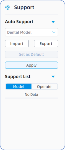
• Auto Support: Primarily consists of three sub-functions: Support Script List, Script Operations, and the Auto-Add entry point.
Support Script List: This list contains various built-in proprietary support scripts preconfigured for different dental applications. Each application has its own dedicated support script, which differs in underlying logical functions and specific parameter settings. Users can click the "..." icon next to a default script to view the detailed parameters in the list.
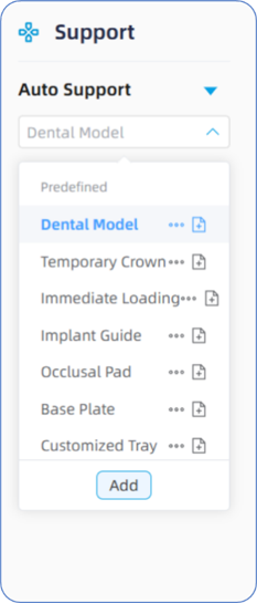
In addition, if users need to add a new support script, they can use the following method.
· Click the "Copy" button next to a default support script. After duplicating the default script, the system will pop up a dialog box displaying the copied support parameters, allowing users to edit and modify them.
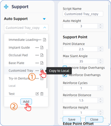
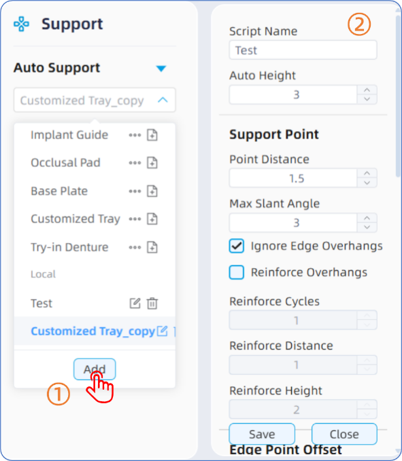
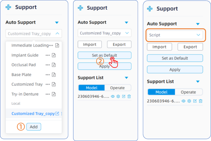
- Click the "Add" button located at the bottom of the support script list drop-down menu to create a new script based on the default support configuration, and then proceed with editing.
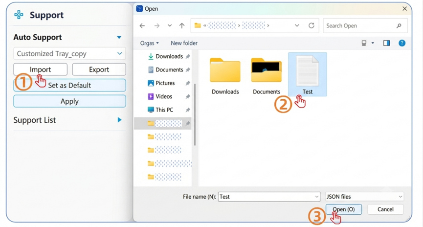
- Click the "Import" button located below the support script list to import a support script file. Users can either use the imported script directly or click the edit button on its right side to make further adjustments and modifications.
Please note:
1. The custom support scripts added by users through the three methods mentioned above will permanently remain in the support list and will not be lost even during software version upgrades, unless they are manually deleted.
If a newly added script needs to be set as the default script for a specific application, once the user selects that designated application, the default support script will display directly within the primary list area without the need to open the drop-down menu. This significantly streamlines the subsequent "Process Planning -> Auto Support" operation. Additionally, the built-in support scripts supplied with the software have undergone extensive data validation and testing, and users can utilize them directly with confidence. If you need to create a new script and set it as the default, it should be done under the guidance of professional technical support personnel.
2.
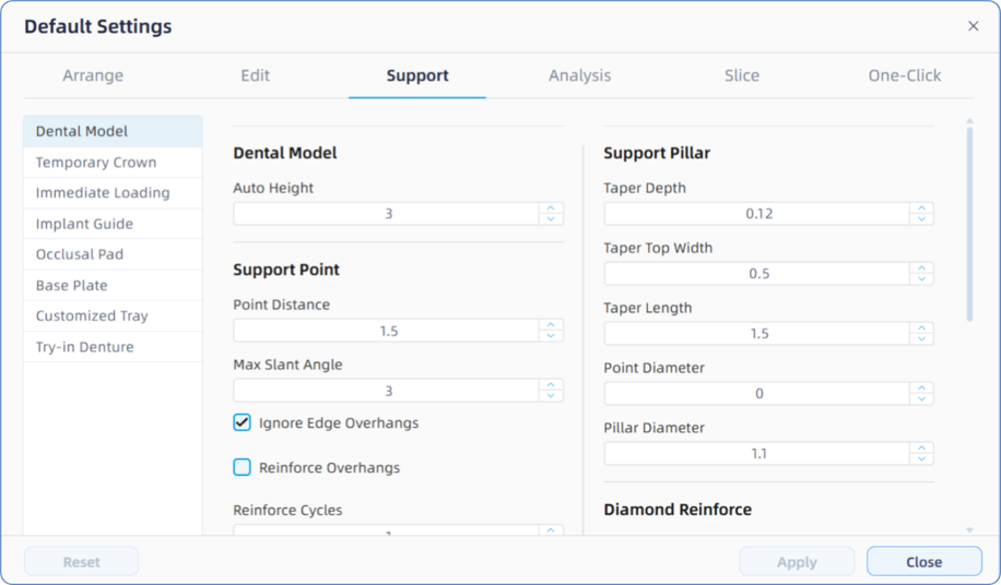
Please note that the configuration of the designated support script here will not apply to the "One-Click Processing" function. If you need to modify the default support parameters for a specific application within the One-Click Processing feature, you must perform the modifications and adjustments under the path "Default Parameter Management -> Add Support -> Dental Model".
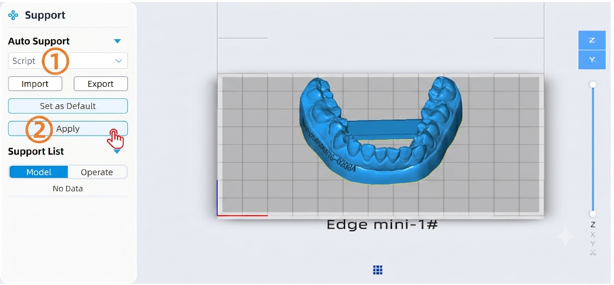
If users need to share an edited support script with others, they can click the "Export Script" button to export the support script file in JSON format. Once the user selects the required support script from the support script list, they can click the "Apply" button to automatically add supports with a single click, and the corresponding model name and support information will be displayed within the support list.
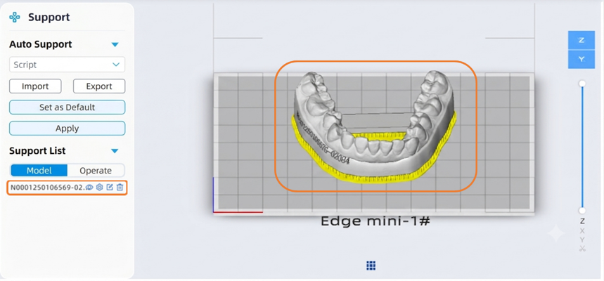
· Support List: Displays the model files to which supports have already been added. To the right of each file name, there are four operation buttons: "Show/Hide", "Edit Script", "Edit Support Points", and "Delete Support".
1. Show/Hide: A single click will hide the added supports of the selected model, and clicking it again will make them visible.
2. Edit Script: Used to edit the script parameters for the current model. Please note that the support script parameters modified here only apply to this specific model instance and will not override or sync back to the global preset support script templates.
3. Edit Support Points: After clicking the "Edit Support Points" button, the camera viewport will automatically switch and focus on the optimal face for support editing. To add support points, single-click the left mouse button on areas of the model surface where no supports are present. To delete support points, single-click an existing support point to remove it, or hold down the Ctrl key while dragging the mouse to draw a bounding box for batch deletion. Please note that: Among the support points, yellow points represent overhang points (the geometric lowest points of the model file at its current orientation). Theoretically, overhang points cannot be deleted and must be supported; otherwise, they will form "isolated islands" during printing, which easily leads to print failure. Blue points represent derivative points (auxiliary support points that propagate outward from the overhang points toward the margins), which users can evaluate and selectively delete based on practical printing requirements.
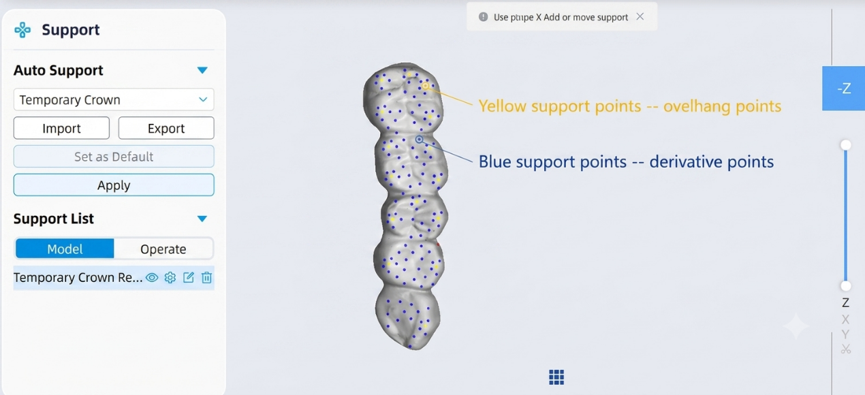
- The bounding-box batch deletion only applies to blue derivative points and excludes yellow overhang points. Overhang points must be clicked manually one by one to be deleted. Please note: If a user deletes a yellow overhang point, an error or warning will be triggered under the "Support Detection" section during the subsequent printability analysis. Therefore, users are strongly discouraged from deleting yellow overhang points arbitrarily.
- Blue derivative points can be trimmed or deleted appropriately depending on the situation. Users can selectively remove or add derivative points based on their practical printing experience and specific application requirements.
4. Delete Support: Clicking this button will delete all supports currently added to the selected model, and the support record for this model will be simultaneously removed from the support list.
The support script parameters and their functional descriptions are detailed below:
|
Name |
Default value |
Description |
Illustration |
|
Script Name |
****
|
The name of the support script. |
—— |
|
Auto Elevate |
3 |
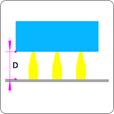
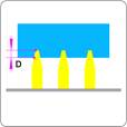
The vertical distance between the lowest point of the model and the build platform. Upon import, the model is placed directy on the platform (0 mm height) by default; |
|
|
Support Points (Group Header) |
|||
|
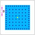
Support Point Spacing |
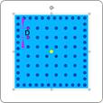
1.5 |
The distance between adjacent support points on the model surface. |
|
|
Max Overhang Angle |
35 |
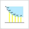
The angle between the model's overhang surface and the horizontal build platform. Supports will be generated when the angle is less than the set value, and omitted otherwise. |
|
|
Ignore Edge Overhangs |
√ |
Description: Primarily used to filter out minor protruding structures on the model edges (such as raised labels or text engraving). When enabled, the algorithm will not generate supports on these micro-protrusions. |
—— |
|
Reinforce Overhangs (Default: Unchecked)) |
|||
|
Reinforcement Rings |
1 |
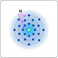
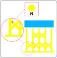
The number of concentric reinforcement rings extending outward from the lowest point of the model. |
|
|
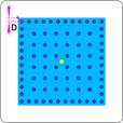
Reinforcement Spacing |
1 |
The linear spacing between adjacent support points within the reinforcement rings. |
|
|
Reinforcement Height |
1 |
The vertical height range extending upward from the lowest point of the model. Support structures within this height threshold will undergo the reinforcement algorithm. |
|
|
Perimeter Point Offset (Group Header) |
|||
|
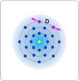
Perimeter Point Spacing |
1 |
The distance between adjacent edge support points generated along the model perimeter. |
|
|
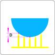
Offset Distance |
0.5 |
Description: The safety clearance distance between the actual model edge and the outermost support points. If the algorithm detects that the model edge feature is smaller than this value, the offset will not be applied. |
|
|
Support Pillar (Group Header) |
|||
|
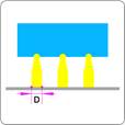
Penetration Depth |
0.15 |
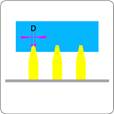
The distance that the support tip penetrates into the model solid body. |
|
|
Top Width |
0.45 |
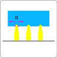
The diameter of the contact tip at the top of the support. |
|
|
Tip Length |
1.5 |
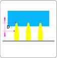
Description: The length of the tapered tip section at the top of the support. |
|
|
Contact Ball Diameter |
0 |
The diameter of the contact ball at the support tip. Setting it to 0 mm disables the ball contact feature. |
|
|
Pillar Diameter |
1.2 |
The diameter of the main body of the support pillar. |
|
|
Cross-Bracing / Diamond Reinforcement (Group Header) |
|||
|
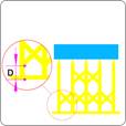
Bracing Height |
3 |
The vertical distance between the lowest point of the reinforcing cross-strut network and the lowest point of the base raft. |
|
|
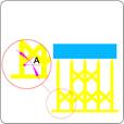
Bracing Angle |
45 |
The angle between the reinforcing cross-struts and the horizontal build platform surface. |
|
|
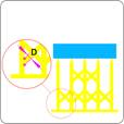
Strut Diameter |
0.6 |
The circumscribed circle diameter of the cross-bracing strut |
|
|
Strut Segments |
6 |
The number of sides for the cross-sectional polygon of the bracing strut |
|
|
Raft / Base (Group Header) |
|||
|
Perimeter Outset |
1 |
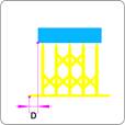
The outward offset distance of the base raft margin relative to the vertical projection of the model solid onto the build platform. |
|
|
Raft Height |
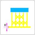
0.5 |
The |
|